動画や音声周りの情報まとめ
ビデオ再生
デバイスについて
4極アナログジャック 4極の順番は、根本から、
Video Ground Right Leftです。
omxplayer
man
omxplayer -- Raspberry Pi command line OMX playerOMXPlayer is a commandline OMX player for the Raspberry Pi. It was developed as a testbed for the XBMC Raspberry PI implementation and is quite handy to use standalone.
非常に高速で、綺麗に表示される。
オーディオの指定は、 hdmi と local(アナログ) のみ。
USBオーディオなどは指定できない。
--loop で再すると、プロセスとして omxplayer.bin と omxplayer の2つが動く。
修了する場合は、両方を kill する。
mplayer
man
mplayer2 - movie player
オーディオの指定は、色々できる(雑)
webmの再生が可能です。
VLC
これから調査
オーディオ再生
デバイスについて
Raspberry pi 2 modebl 2 と 3 で、可能なオーディオ再生方法。
デバイスの情報の取得
 $ aplay -l
**** ハードウェアデバイス PLAYBACK のリスト ****
カード 0: ALSA [bcm2835 ALSA], デバイス 0: bcm2835 ALSA [bcm2835 ALSA]
  サブデバイス: 8/8
  サブデバイス #0: subdevice #0
  サブデバイス #1: subdevice #1
  サブデバイス #2: subdevice #2
  サブデバイス #3: subdevice #3
  サブデバイス #4: subdevice #4
  サブデバイス #5: subdevice #5
  サブデバイス #6: subdevice #6
  サブデバイス #7: subdevice #7
カード 0: ALSA [bcm2835 ALSA], デバイス 1: bcm2835 ALSA [bcm2835 IEC958/HDMI]
  サブデバイス: 1/1
  サブデバイス #0: subdevice #0
カード 1: MicroII [Audio Advantage MicroII], デバイス 0: USB Audio [USB Audio]
  サブデバイス: 1/1
  サブデバイス #0: subdevice #0
など。
aplay
aplay -q -D plughw:0,1 bou.wav
などします。
mpg123
# USBでの再生
$ mpg123 -o alsa -a hw:1 -vC jazz_01.mp3

# アナログ or HDMI での再生
$ mpg123 -o alsa -a hw:0 -vC jazz_01.mp3
など
の場合だと、
0 : アナログかHDMIの優先設定されている方
1 : USB
になります。
優先設定は
$ amixer cset numid=3 1 # 1:アナログ, 2:HDMI
などして変えます。
OpenJTalk で、文字を読ませるテスト
OpenJTalk で、文字を読ませるテスト
インストール
$ sudo apt-get install open-jtalk
$ sudo apt-get install open-jtalk-mecab-naist-jdic hts-voice-nitech-jp-atr503-m001
起動スクリプト
#!/bin/bash
HV=/usr/share/hts-voice/nitech-jp-atr503-m001/nitech_jp_atr503_m001.htsvoice
tempfile="./tempfile"

option="-x /var/lib/mecab/dic/open-jtalk/naist-jdic -m $HV -ow $tempfile"

if [ -z "$1" ] ; then
  open_jtalk $option
else
  if [ -f "$1" ] ; then
    open_jtalk $option $1
  else
    echo "$1" | open_jtalk $option
  fi
fi

#aplay -q $tempfile
aplay --quiet -D plughw:1,0 $tempfile
rm -f $tempfile
テスト
$ ./jsay "本日は晴天なり"
音声の追加1 公式サンプル
$ wget https://sourceforge.net/projects/mmdagent/files/MMDAgent_Example/MMDAgent_Example-1.6/MMDAgent_Example-1.6.zip
$ unzip MMDAgent_Example-1.6.zip
$ cd MMDAgent_Example-1.6/Voice/
$ sudo cp -R mei /usr/share/hts-voice/
$ find /usr/share/hts-voice/ -name *htsvoice
/usr/share/hts-voice/mei/mei_normal.htsvoice
/usr/share/hts-voice/mei/mei_angry.htsvoice
/usr/share/hts-voice/mei/mei_bashful.htsvoice
/usr/share/hts-voice/mei/mei_happy.htsvoice
/usr/share/hts-voice/mei/mei_sad.htsvoice
/usr/share/hts-voice/nitech-jp-atr503-m001/nitech_jp_atr503_m001.htsvoice
HV=/usr/share/hts-voice/nitech-jp-atr503-m001/nitech_jp_atr503_m001.htsvoice を変更すると、変わる。
音声の追加2 配布データ
htsvconv ファイル形式で配付されていればそのまま指定する。
MMDAgent 音響データファイル郡の場合は、こちら様のお世話になったりして、作成して設置する。
USBスピーカー
USBスピーカー で音鳴らすためのメモ
aplay
$ aplay -l
**** ハードウェアデバイス PLAYBACK のリスト ****
カード 0: ALSA [bcm2835 ALSA], デバイス 0: bcm2835 ALSA [bcm2835 ALSA]
  サブデバイス: 8/8
  サブデバイス #0: subdevice #0
  サブデバイス #1: subdevice #1
  サブデバイス #2: subdevice #2
  サブデバイス #3: subdevice #3
  サブデバイス #4: subdevice #4
  サブデバイス #5: subdevice #5
  サブデバイス #6: subdevice #6
  サブデバイス #7: subdevice #7
カード 0: ALSA [bcm2835 ALSA], デバイス 1: bcm2835 ALSA [bcm2835 IEC958/HDMI]
  サブデバイス: 1/1
  サブデバイス #0: subdevice #0
カード 1: MicroII [Audio Advantage MicroII], デバイス 0: USB Audio [USB Audio]
  サブデバイス: 1/1
  サブデバイス #0: subdevice #0

$ aplay -D plughw:1,0 bou.wav
mplay
$ cat /proc/asound/cards
 0 [ALSA           ]: bcm2835 - bcm2835 ALSA
                      bcm2835 ALSA
 1 [MicroII        ]: USB-Audio - Audio Advantage MicroII
                      C-Media INC. Audio Advantage MicroII at usb-3f980000.usb-1.2, full speed
$ mplayer -ao alsa:device=hw=1.0 jazz_01.mp3
omxplayer
USBデバイスは非対応?
起動時に実行される X window を設定し、ブラウザ装置にする
起動時に実行される X window を設定して、目的のアプリのみをフルスクリーンで表示させる。
練習
まずは、startx で、手動で xwindow を立ち上げる際の設定ファイルに触れる。
# apt-get install x11-xserver-utils unclutter
設定ファイル .xinitrc を作成する
$ cp /etc/X11/xinit/xinitrc ~/.xinitrc
中身を編集する。
$ cat .xinitrc
#!/bin/sh

# /etc/X11/xinit/xinitrc
#
# global xinitrc file, used by all X sessions started by xinit (startx)

# invoke global X session script
. /etc/X11/Xsession

xset s off
xset -dpms
xset s noblank
など。
Chromium インストール
apt-get install でサクッとは入らない。
こちらを参考にする。
Raspberry Pi • View topic - Guide: Chromium 51 on Raspbian Jessie
$ wget -qO - http://bintray.com/user/downloadSubjectPublicKey?username=bintray | sudo apt-key add -
$ echo "deb http://dl.bintray.com/kusti8/chromium-rpi jessie main" | sudo tee -a /etc/apt/sources.list
$ sudo apt-get update
$ sudo apt-get install chromium-browser rpi-youtube -y

$ chromium-browser --app=http://www.google.co.jp --window-size=1024,768
chromium を全画面起動
Startx > Chromium 全画面
$ cat .xinitrc
#!/bin/sh

# /etc/X11/xinit/xinitrc
#
# global xinitrc file, used by all X sessions started by xinit (startx)

# invoke global X session script
#. /etc/X11/Xsession

xset s off
xset s noblank
xset -dpms

chromium-browser --kiosk --start-maximized --user-data-dir http://google.co.jp/
なお、 --kiosk モードで起動すると、画面上部に黒い隙間が出来ます。
キャッシュファイル
~/.cache/chromium に保存されます。
毎回削除したりします。
ログファイル
~/.config/chromium/Default/Preferences に保存されます。
正常に終了したかどうかチェックしているので、exited_cleanly を True に書き換えたりします。
書き換えのタイミングですが、書き換えの次の行でブラウザを起動すると、どうも上手く行かなかったりするので、他の処理を先に入れたりしました。
自動ログイン~全画面起動
自動ログインの設定
- raspi-config で グラフィカルログインを選択しておく
- ログインユーザーを設定する
GUI自動ログインの場合には、
/etc/systemd/system/autologin@.service ではなく、
/etc/lightdm/lightdm.conf が読み込まれている模様。
- ログインユーザーの autostart を編集
$ cat ~/.config/lxsession/LXDE-pi/autostart
# Edit..
#@lxpanel --profile LXDE-pi
#@pcmanfm --desktop --profile LXDE-pi
#@xscreensaver -no-splash

# Add..
@unclutter
@xset s off
@xset s noblank
@xset -dpms
@/usr/bin/chromium-browser --kiosk --start-maximized --user-data-dir http://google.co.jp/
なお、 --kiosk モードで起動しても、画面上部に黒い隙間は出来ません。
Python で WEB Server > 諦めて apache
Python で簡単にWEBサーバーを立てられるので、試す。
Lチカを目指します!
SimpleHTTPServer
CGIは動かないシンプルなもの。
Python 2系列
$ sudo python -m SimpleHTTPServer 80
CGIHTTPServer
CGIが動きます。
$ sudo python -m CGIHTTPServer 80
ファイル作成
#!/usr/bin/env python
# -*- coding: utf-8 -*-

import cgitb
cgitb.enable()

print "Content-Type: text/html;charset=utf-8"
print

print "Hello World!"
パーミッションを 755 にする
$ chmod 755 index.py
GPIO を触る
せっかくのpython なので、GPIO も触ってみる。
ところが import RPi.GPIO as GPIOなどすると、ROOT で実行しなさいとエラーが出る。
これは、 nobody で cgi が起動しているからだ。
20.20. CGIHTTPServer — CGI 実行機能付き HTTP リクエスト処理機構 — Python 2.7.13 ドキュメント
さて、どうしたものか・・・。
試したこと その1(NG)
nobody を group gpio に入れる
コマンドラインからは、 sudo -u nobody ./index.py などで動作するが、cgi からは動かない。
print(os.getuid())
commands.getoutput("cat /sys/class/gpio/gpio4/value")
で、 nobody (65534) で有ることの確認をとりつつ動かしましたが、
cat: /sys/class/gpio/gpio4/value: 許可がありません
を、得る。
どこで止まっているのか不明。
試したこと その2(NG)
Python3 で試す。
pip3 install wiringpi2
sudo python3 -m http.server –cgi 80
FileNotFoundError: [Errno 2] No such file or directory: ‘cat /sys/class/gpio/gpio4/value’
/bin/cat: /sys/class/gpio/gpio4/value: 許可がありません
諦めて apache
諦めて apache2 でやります。
- apache2 install
- mod python とか色々入れます
$ sudo apt-get install libapache2-mod-python
/etc/apache2/envvars
実行ユーザを変えてしまう
/etc/apache2/envvars
で、
export APACHE_RUN_USER=pi
export APACHE_RUN_GROUP=pi
などしてしまう。
<Directory /home/pi/public_html>
        Options Indexes FollowSymLinks
        AllowOverride None
        Require all granted

        AddHandler mod_python .py
        PythonHandler mod_python.publisher
        PythonDebug On

        Options +ExecCGI
        AddHandler cgi-script .py
</Directory>
ハマり所
cgi-bin の許可
permission 755 にし忘れる
これで、GPIOに触れる様になった。
ただし、GPIOの初期設定には、やはりroot権限が必要なのが注意だ。
コーディングとアパッチの圧縮OFF
手順
$ cat ../set_gpio_pins.sh
#!/bin/bash
/usr/local/bin/gpio export 4 out
/usr/local/bin/gpio -g mode 4 out
チカチカ終了を待たずに、htmlを吐き出せるように、スレッドを使用しています。
ここで注意が必要なのは、Pythonレベルでバッファリングを指定無くても、Apacheは、初期設定のまま使っていると、Gzip圧縮してくれるので、結果的にバッファリングされます。
# cat /etc/apache2/mods-enabled/deflate.conf
<IfModule mod_deflate.c>
        <IfModule mod_filter.c>
                # these are known to be safe with MSIE 6

# Changed
                #AddOutputFilterByType DEFLATE text/html text/plain text/xml

                # everything else may cause problems with MSIE 6
                AddOutputFilterByType DEFLATE text/css
                AddOutputFilterByType DEFLATE application/x-javascript application/javascript application/ecmascript
                AddOutputFilterByType DEFLATE application/rss+xml
                AddOutputFilterByType DEFLATE application/xml
        </IfModule>
</IfModule>
text/html に対して、圧縮をOFFにしました。
それを前提のコード。
#!/usr/bin/python -u
# -*- coding: utf-8 -*-
import sys
import wiringpi as wp
import time
import threading

from datetime import datetime

import cgi
import cgitb
cgitb.enable()

PIN     = 4

class MyThread(threading.Thread):
        def __init__(self):
                threading.Thread.__init__(self)

        def run(self):
                time.sleep(1)
                io = wp.GPIO(wp.GPIO.WPI_MODE_GPIO_SYS) # WPI_MODE_PINS WPI_MODE_GPIO WPI_MODE_GPIO_SYS WPI_MODE_PHYS WPI_MODE_PIFACE

                counter = 0
                while counter < 10:
                        io.digitalWrite(PIN,io.HIGH)
                        time.sleep(0.2)
                        io.digitalWrite(PIN,io.LOW)
                        time.sleep(0.2)
                        counter += 1

th = MyThread()
th.setDaemon(True)
th.start()

form = cgi.FieldStorage()
action          = form.getvalue('action','')

print("Content-Type: text/html;charset=utf-8")
print("\r\n\r\n")

print("""
<html>
<body>
<a href="?action=led">LED</a>
{action}
</body>
</html>
"""[1:-1].format(**vars()))

print( datetime.now().strftime("%Y/%m/%d %H:%M:%S") )
th.join()
ちゃんと、先にHTMLが出力されてから、チカチカします。
距離センサー GP2Y0A710K を試す
GP2Y0A710K を試す。
データ
特徴
・赤外線とPSD(position sensitive detector)を使用し非接触で距離を測定することができます。
・1m~5.5mまで測定可能です。
・超音波方式より狭い領域での測距が可能です。(音響反射等の影響を受けない)
・距離に反比例した出力電圧。
わかりやすいアナログ出力です。
主な仕様
・寸法:58×17.6×22.5mm
・消費電流:30mA(typ)
・電源電圧:DC5VDC
(4.5~5.5VDC)


配線がややこしい。
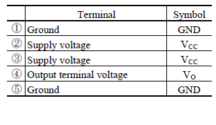
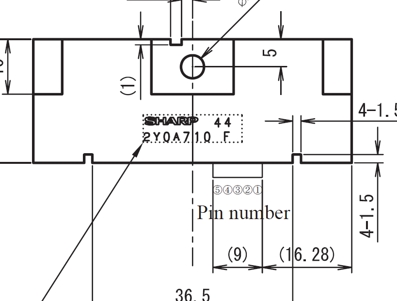
図を見て、スタンプが有る側から見て、右が 1 だ!
ケーブルを挿すとこうなる。
右から1,2,3,4,5 だから、
1,4 は GND, 2,3(青と黒) は Vcc, 4(白) は Vo だ!


配線
ADコンバーターは、MCP3008(10bit)を使用しています。
MCP3008 Vdd(16), Vref(15) -> Raspberry Pi 3.3v
MCP3008 AGND(14), DGND(9) -> Raspberry Pi GND
MCP3008 CLK(13)           -> Raspberry Pi GPIO 11 (SCLK)
MCP3008 DOUT(12)          -> Raspberry Pi GPIO 9 (MISO)
MCP3008 DIN(11)           -> Raspberry Pi GPIO 10 (MOSI)
MCP3008 CS/SHDN(10)       -> Raspberry Pi GPIP 8 (CE0)
MCP3008 と、ADコンバーターとRPIの接続。
MCP3008 Vcc -> Raspberry Pi 5v
MCP3008 GND -> Raspberry Pi GND
MCP3008 Vo  -> MCP3008 CH0(1)
別に、MCP3008 の CH0 じゃなくて、1でも7でも構いません。
下記 channel がそれに対応します。
コーディング
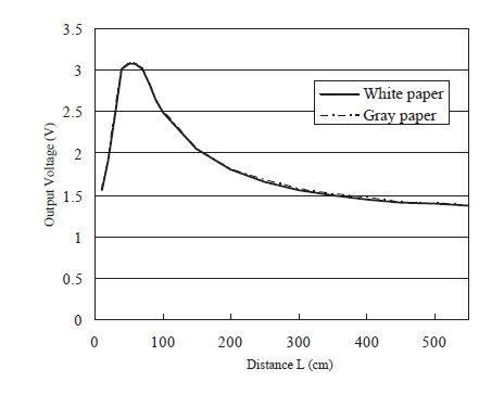
距離の計算は、こちらを使わせていただきました。
$ cat GP2Y0A710K.py
#!/usr/bin/env python

import time
import sys
import spidev

spi = spidev.SpiDev()
spi.open(0,0)

channel = 0

# MCP3008 10bit
def readAdc(channel):
        adc = spi.xfer2([1,(8+channel)<<4,0])
        data = ((adc[1]&3) << 8) + adc[2]
        return data

def convertVolts(data):
        volts = (data * 3.3) / float(1023)
        volts = round(volts,4)
        return volts

def convertDistance(volts):
#       dist =  250 / volts
        dist = ( 9.5974 / volts ) -3.0086
        return dist

if __name__ == '__main__':
        try:
                while True:
                        data = readAdc(channel)
                        volts = convertVolts(data)
                        dist = convertDistance(volts)

                        print("adc  : {:8}".format(data))
                        print("volts: {:8.2f}".format(volts))
                        print("dist : {:8}".format(dist))

                        time.sleep(1)

        except KeyboardInterrupt:
                pass

spi.close()
sys.exit(0)
追記
参考資料を見ると
7-8 電源ライン安定化の為、製品近傍のVcc-GNDに 10μF以上のバイパスコンデンサを、、、
7-9 350ma以上の電源を・・・
と書いてあった。
RPI 5v は、私の場合 2.0A 給電しているから、 2000 - 900 = 1100mA だせるから、問題ない。
距離センサー GP2Y0A21 を試す
距離センサー GP2Y0A21 を試す
赤外線を使用した測距モジュール
赤外線LEDとPSD(position sensitive detector)を使用して、非接触で距離を検出することができます。
・測距範囲:10~80cm
・出力:アナログ電圧出力
・寸法:29.5×13×13.5mm
・用途:ロボット・アミューズメント等
・電源:4.5~5.5V
※付属ケーブルの単品販売もございます→ C-05684
※検出距離が違う測距モジュールもあります。
GP2Y0A02YK(20cm~150cm)<I-03158>
GP2Y0A710K(1m~5.5m) <I-03157>
とにかく注意すべきは、最初からついてきたケーブルの、赤 が GND で、黒 が Vcc であること。
私は、赤と黒を切断して、繋ぎ直しました。
配線
アナログ電圧主力なので、ADコンバーターに刺します。8ビットADコンバーターです。
3(4番目)に刺しました。

コーディング
#!/usr/bin/env python

import time
from datetime import datetime as dt
import sys
import spidev

spi = spidev.SpiDev()
spi.open(0,0)


def readAdc(channel):
        adc = spi.xfer2([6+((channel&4)>>2),(channel&3)<<6,0])
        data = ((adc[1]&15) << 8) + adc[2]
        return data

def convertVolts(data):
        volts = (data * 3.3) / float(4095)
        volts = round(volts,4)
        return volts

def convertDistance(volts):
        dist =  60 / volts
        return dist

if __name__ == '__main__':
        try:
                while True:
                        tstr    = dt.now().strftime('%Y/%m/%d %H:%M:%S')

                        data = readAdc(3)
                        volts = convertVolts(data)
                        dist = convertDistance(volts)

                        print("adc  : {:8}".format(data))
                        print("volts: {:8.2f}".format(volts))
                        print("dist : {:8}".format(dist))

                        time.sleep(1)

        except KeyboardInterrupt:
                spi.close()
                sys.exit(0)
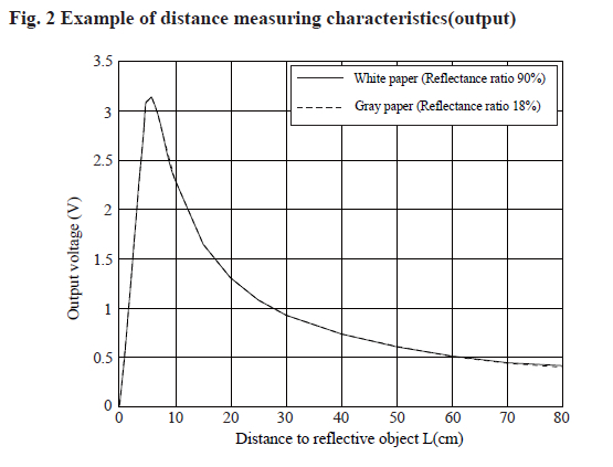
距離の計算が、よくわからない。
というか、そもそも、秋月からリンクが貼られているデータシートと、シャープのデータシートと、
同梱されていた印刷物の資料の、グラフが異なる。
同梱されていた参考資料では、 15cm で、最高の 2.8v に成るかのような表記だ。
ものすごくざっくりだと、距離 cm = 60 / volts なのかな・・・。