Raspberry pi Zero で オフィス環境の可視化 その2
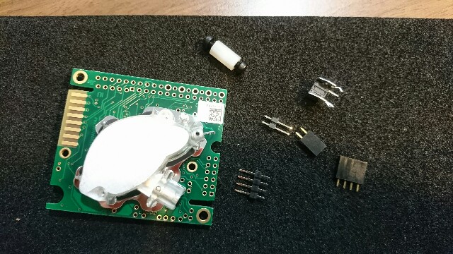

K30 CO2 Sensor SENSEAIR
UART でつなぎます。
$ pip install pyserial
$ sudo systemctl stop serial-getty@ttyAMA0.service
コーディング
前回の使い回し。
#!/usr/bin/env python
# -*- coding: utf-8 -*-

import serial
import time

ser = serial.Serial("/dev/ttyAMA0")
#print "Serial Connected!"
ser.flushInput()
#time.sleep(0.5)

while True:
        ser.write("\xFE\x44\x00\x08\x02\x9F\x25")
        time.sleep(0.01)
        resp = ser.read(7)
        high = ord(resp[3])
        low = ord(resp[4])
        co2 = (high*256) + low
        if co2 > 1:
                print(str(co2))
        time.sleep(5)
音絡み
sudo apt-get install python-alsaaudio
cat /proc/asound/modules
/etc/modprobe.d/alsa-base.conf で、 options snd-usb-audio index=0にしてあげる。
Raspberry pi Zero で オフィス環境の可視化 その1
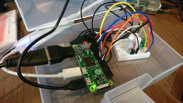
Raspberry Pi Zero にセンサーを付けて、各種データを集める。
登場するセンサー
- 温湿度センサー AM2302 > AM2320 に変更
- 気圧センサー SCP1000-D01
- CO2センサー K30
Raspberry pi Zero セットアップ
Micor SDカードを SDformatter でフォーマット
公式サイトからダウンロードしてきた 2016-11-25-raspbian-jessie-lite を Win32DiskImager で焼く
挿してBoot
OS 設定
- 色々入れる
rpi-update, vim, build-essential, python-dev
alias vi='vim'
- international
locale, timezone, keybord [Generic 105-Key(Intel) PC] [japanese]
- 日本語フォントとターミナル
apt-get install -y fonts-takao ibus-mozc jfbterm
- SSH ON
systemctl enable ssh
- 新規ユーザーの作成とグループへの追加
piからsudo剥奪 sudo gpasswd -d pi sudo
# usermod -G pi,adm,dialout,cdrom,sudo,audio,video,plugdev,games,users,input,netdev,spi,i2c,gpio _USERNAME_
# visudo
- IP固定
/etc/dhcpcd.conf
interface eth0
static ip_address=192.168.100.88/24
static routers=192.168.100.1
static domain_name_servers=192.168.100.1
GPIOピン付
はんだ付けする。
40PIN メスを付けました。
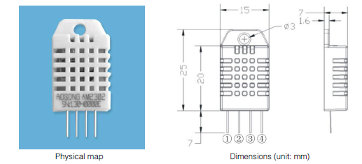
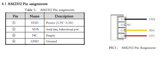
AM2302
Special instructions of the single-bus communication:
1.Typical application circuit recommended in the short cable length of 30 meters on the 5.1K pull-up resistor pullup resistor according to the actual situation of lower than 30 m.
2.With 3.3V supply voltage, cable length shall not be greater than 100cm. Otherwise, the line voltage drop will lead to the sensor power supply, resulting in measurement error.
3.Read the sensor minimum time interval for the 2S; read interval is less than 2S, may cause the temperature and humidity are not allowed or communication is unsuccessful, etc..
4.Temperature and humidity values are each read out the results of the last measurement For real-time data that need continuous read twice, we recommend repeatedly to read sensors, and each read sensor interval is greater than 2 seconds to obtain accuratethe data.
5.1kΩ のプルアップ抵抗が必要ですが、手元にないので、4.7kΩ を入れました。
動作テスト
adafruit さんのスクリプトをありがたく使わせて頂く。
$ git clone https://github.com/adafruit/Adafruit_Python_DHT.git
$ git clone https://github.com/adafruit/Adafruit_Python_DHT.git
$ cd Adafruit_Python_DHT
$ sudo python setup.py install
$
$ cd examples/
$ sudo python ./AdafruitDHT.py 2302 4
Temp=24.9*  Humidity=46.0%
動いた。
コーディング
#!/usr/bin/python
import sys
import time
import Adafruit_DHT

sensor = Adafruit_DHT.AM2302
pin = 4

if __name__ == '__main__':
        try:
                while 1:
# Try to grab a sensor reading.  Use the read_retry method which will retry up
# to 15 times to get a sensor reading (waiting 2 seconds between each retry).
                        humidity, temperature = Adafruit_DHT.read_retry(sensor, pin)

# Un-comment the line below to convert the temperature to Fahrenheit.
                        # temperature = temperature * 9/5.0 + 32

# Note that sometimes you won't get a reading and
# the results will be null (because Linux can't
# guarantee the timing of calls to read the sensor).
# If this happens try again!

                        if humidity is not None and temperature is not None:
                                print( 'Temp={0:0.1f}dc'.format(temperature) )
                                print( 'Humidity={0:0.1f}%'.format(humidity) )
                                # print('Temp={0:0.1f}D  Humidity={1:0.1f}%'.format(temperature, humidity))
                        else:
                                print('Failed to get reading. Try again!')
                        time.sleep(3)

        except KeyboardInterrupt:
                sys.exit(0)
動かしてみて(追記)
数日運用して気がついたのですが、2つ問題が発生。
1. 結構簡単に止まる
2. 変に低い値が出る
電圧低下が原因とも思えないし、、、調査中です。
3.3v でも動作するので、
Vcc を GPIO にして、定期的に 通電/遮断 を繰り返せば、何とかごまかせますが、おかしいと思う。
AM2320
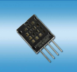
上記問題点をクリアできなかったので、AM2320 に乗り換えてみます。
配線
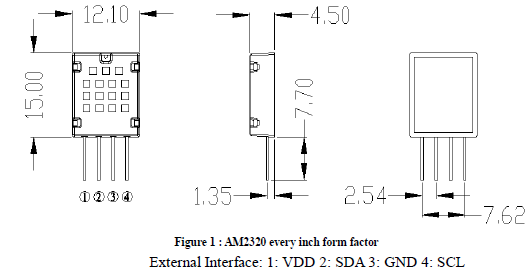
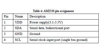
AM2302 とは異なり、I2C でつなぎます。
動作チェック
$ lsmod | grep i2c
i2c_bcm2708             5740  0
i2c_dev                 6578  2
$ ls /dev/i2c-*
/dev/i2c-1
$ sudo i2cdetect -y 1
     0  1  2  3  4  5  6  7  8  9  a  b  c  d  e  f
00:          -- -- -- -- -- -- -- -- -- -- -- -- --
10: -- -- -- -- -- -- -- -- -- -- -- -- -- -- -- --
20: -- -- -- -- -- -- -- -- -- -- -- -- -- -- -- --
30: -- -- -- -- -- -- -- -- -- -- -- -- -- -- -- --
40: -- -- -- -- -- -- -- -- -- -- -- -- -- -- -- --
50: -- -- -- -- -- -- -- -- -- -- -- -- -- -- -- --
60: -- -- -- -- -- -- -- -- -- -- -- -- -- -- -- --
70: -- -- -- -- -- -- -- --
$ sudo i2cdetect -y 1
     0  1  2  3  4  5  6  7  8  9  a  b  c  d  e  f
00:          -- -- -- -- -- -- -- -- -- -- -- -- --
10: -- -- -- -- -- -- -- -- -- -- -- -- -- -- -- --
20: -- -- -- -- -- -- -- -- -- -- -- -- -- -- -- --
30: -- -- -- -- -- -- -- -- -- -- -- -- -- -- -- --
40: -- -- -- -- -- -- -- -- -- -- -- -- -- -- -- --
50: -- -- -- -- -- -- -- -- -- -- -- -- 5c -- -- --
60: -- -- -- -- -- -- -- -- -- -- -- -- -- -- -- --
70: -- -- -- -- -- -- -- --
コーディング
こちらを基に、コーディング。
温湿度センサAM2320をRaspberry Pi 3で使用する|wizqro.net
データシートにもには、まだ目を通して居ませんが、
i2cdetect -y 1 を繰り返すたびに、出てきたり出てこなかったりを繰り返していのは、先にreadする必要があるのかな?
#!/usr/bin/env python
# -*- coding: utf-8 -*-

import sys
import time
import smbus

i2c = smbus.SMBus(1)
address = 0x5c

if __name__ == '__main__':
        try:
                while 1:
                        # センサsleep解除
                        try:
                            i2c.write_i2c_block_data(address,0x00,[])
                        except:
                            pass

                        # 読み取り命令
                        time.sleep(0.003)
                        i2c.write_i2c_block_data(address,0x03,[0x00,0x04])

                        # データ受取
                        time.sleep(0.015)
                        block = i2c.read_i2c_block_data(address,0,6)
                        humidity = float(block[2] << 8 | block[3])/10
                        temperature = float(block[4] << 8 | block[5])/10

                        print('Temp={0:0.1f}D  Humidity={1:0.1f}%'.format(temperature, humidity))
                        time.sleep(10)

# SQL にデータを投げます
# ...

        except KeyboardInterrupt:
                sys.exit(0)
実際には、SQLにデータを投げる処理も行っています。
注意点 Repeated Start Condition
Raspberry Pi で I2C の Repeated Start Condition を有効化 - Rabbit Note
/etc/modprobe.d/i2c.conf
options i2c_bcm2708 combined=1
データシートにも Repeated Start condition setup time 4.7 と表記がある。
SCP1000-D01


SPI通信なので、まず有効にします。
raspi-config > advanced > spi
Wiringpi をインストール
$ git clone git://git.drogon.net/wiringPi
$ cd wiringPi/
$ ./build
以下のサイトを参考にさせていただいております。
ArduinoにSPI通信を行う機器を接続する(6) - フィジカル・コンピューティング
特に、コードは「意伝子発信器」さんのコードを改変して作りました。
レジスタ
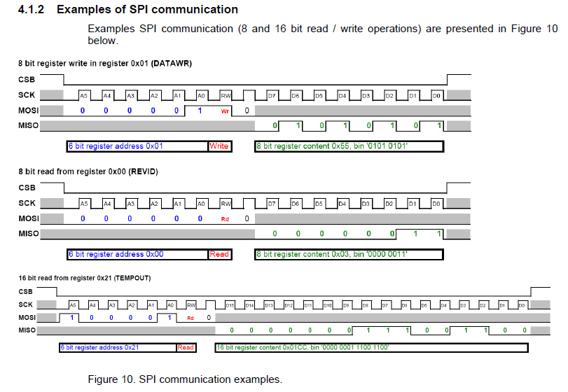
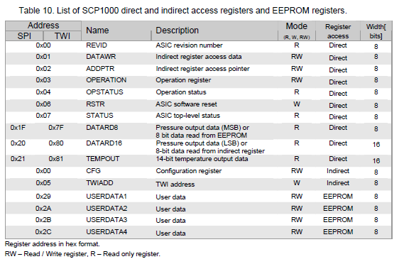
サンプルを見ると、
レジスタ + 1/0 + 0 がひと固まりだとわかる。
B1 は常に 0
B2 は Read=0,Write=1
だ。
Address を、bite にする計算。
例) 0x06 RSTR "ASIC software reset" W Direct 8bits
の場合、
16進数 0x06
2進数 b110
Writeと 0 をお尻に足す b11010
16進数 0x1A
リセット命令 0x06,W,0 b11010, 0x1A
ステータス取得 0x07,R,0, b11100, 0x1C
オペレーションモード設定 0x03,R,0 0x0E
コーディング
とりあえず動くコード
#include<wiringPiSPI.h>
#include<wiringPi.h>
#include<stdio.h>
#include<stdlib.h>

#define SPI_CHANNEL 0
#define SPI_CLK 500000

int main(void){
        double temp, pressure = 0;
        unsigned char buf[3];
        int i,flag1=0, flag2=0;


        //wiringPiライブラリの初期化
        if (wiringPiSetup () == -1){
                return (1) ;
        }

        //SPIデバイスの初期化
        if((wiringPiSPISetup(SPI_CHANNEL, SPI_CLK))<0){
                printf("error SPI\n");
        }

        //ソフトリセットコード
        buf[0] = 0x1a;
        buf[1] = 0x01;
        wiringPiSPIDataRW(SPI_CHANNEL, buf, 2);
        printf("delay...\n");
        delay(60);

        //STATUS確認
        buf[0] = 0x1c;
        buf[1] = 0xff;
        wiringPiSPIDataRW(SPI_CHANNEL, buf, 2);
        printf("STATUS:%02x\n", buf[1]);
        i= buf[1]&0x01;
        if(i == 0){
                flag1 = 1;
                printf("STATUS OK!\n");
        }

        //DATARD8確認
        buf[0] = 0x7c;
        buf[1] = 0xff;
        wiringPiSPIDataRW(SPI_CHANNEL, buf, 2);
        printf("DATARD8:%02x\n", buf[1]);
        i= buf[1]&0x01;
        if(i == 1){
                flag2 = 1;
                printf("DATARD8 OK!\n");
        }


        if(flag1!=1 || flag2!=1){
                printf("Error...\n");
                exit(1);
        }


        //オペレーションレジスタに高精度測定モードを設定
        buf[0] = 0x0e;
        buf[1] = 0x0a;
        wiringPiSPIDataRW(SPI_CHANNEL, buf, 2);

        //メインループ
        while(1){
                //温度の測定
                buf[0] = 0x84;
                buf[1] = 0x00;
                buf[2] = 0x00;
                wiringPiSPIDataRW(SPI_CHANNEL, buf, 3);
                temp = (double)((buf[1] << (8+2)) + (buf[2] << 2)) / 20 / 4;

                //気圧の測定
                buf[0] = 0x7c;
                buf[1] = 0x00;
                wiringPiSPIDataRW(SPI_CHANNEL, buf, 2);
                pressure = buf[1] << 16;
                buf[0] = 0x80;
                buf[1] = 0x00;
                buf[2] = 0x01;
                wiringPiSPIDataRW(SPI_CHANNEL, buf, 3);
                pressure += (buf[1] << 8) + buf[2];
                pressure = pressure / 4 / 100;

                printf("temp %2.2f\n", temp);
                printf("press %4.4f\n", pressure);

                delay(1000);
        }
}
Mbed LPC1114FN28 を試す その2

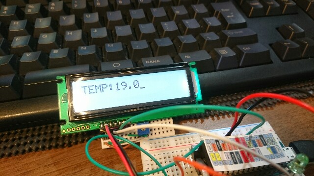
前回、動作確認まで取れたので、早速違うことをやってみましょう。
Raspberry pi の様に、センサーにつないで、値を読み込んでみよう。
、、、と思ったのですが、読み込んだ値を確認するすべがない!
なので、まずはモニターを付けます。
I2C LCDモニター ACM1602NI
以前買った I2C LCDモニター ACM1602NI を使いたいと思います。
LPC1114FN28 には、I2Cも有るし、問題ないでしょう。
けど、一体どう配線して、どういうコードを書けば良いのやら?
配線
I2C SCL と SCL
I2C SDA と SDA
を繋いでみました。
最終的に動いたので、正しそうです。
ライブラリを探す
そこで、Mbedの強みの1つと言われている、他の人が作って公開してくれているライブラリを探してみましょう。
mbed 公式サイトに行って、 "ACM1602NI" で検索します。
検索結果のURL
"Takuo WATANABE" さんのライブラリを発見しました。
早速使います。
"Import into Compiler" をクリックして、インポートするプロジェクトを選択する。
それだけです。
早速利用します。
要点だけに成りますが、
#include "ACM1602NI.h"

ACM1602NI lcd(dp5, dp27);

    lcd.cls();
    lcd.printf("ACM1602NI\n");
    lcd.printf("\n");
など書きます。
温度センサー MCP9700
引き続き、手元にある MCP9700 を使います。
まず、アナログインプットを読み込ませたいので、DP13 に接続しました。
続いて、ライブラリを探します。
MCP9700 Linear Temperature Sensor | Mbed
発見しましたので、import して、使います。
コード
手元に合ったタクトスイッチを入れて、とりあえず動いているコード。
#include "mbed.h"
#include "ACM1602NI.h"
#include "LinearTempSensor.h"

DigitalOut led2(LED2);
DigitalIn mysw(dp17);
LinearTempSensor sensor(dp13);

// I2C pins: p9 = sda, p10 = scl
ACM1602NI lcd(dp5, dp27);


int main() {
    float Vout, Tav, To;

    led2    = 0;
    mysw.mode(PullDown);

    lcd.printf("ACM1602NI\n");
    lcd.printf("\n");
    wait(2);

    while(1) {
        led2    = 1;
        wait(0.2);
        led2    = 0;
        wait(0.2);

        if(mysw.read()==1){
            lcd.cls();
            lcd.printf("TEMP:");
            Vout = sensor.Sense();          // Sample data (read sensor)
            Tav  = sensor.GetAverageTemp(); // Calculate average temperature from N samples
            To   = sensor.GetLatestTemp();  // Calculate temperature from the latest sample
            lcd.locate(5, 0);
            lcd.printf("%4.1f\n", Tav);
            // lcd.printf("Vout:%f  Tav:%f  To:%f\n", Vout, Tav, To);    // Debug print
        }else{
            lcd.cls();
            lcd.printf("Please Push.\n");
        }
        wait(0.2);
    }
}
なお、本来は、こういうコードも、mbedオフィシャルサイトに投稿するのが正しいのでしょうが、
「Mbedってなに?」というレベルだと、そこに到達しませんので、本当のMbed初心者のために、書き残します。
Raspberry pi と比較すると、アナログの値をそのまま読み取れるのは楽です。
ADコンバーターないぶん、配線が少ない。
Thread について
調査中ですが、
Mbed で Thread を使用するには、OS を使うらしい。
Mbed OS を使う方法と、RTOSをインポートする方法が有るらしい。
ですが、
LPC1114FN28 は、
Note: LPC1114FN28 platform doesn't support RTOS due to its flash size. Please do not import mbed-rtos library into your project.
とあり、使えません!
補足
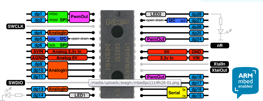
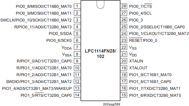
7 VDDA アナログ電源(+3.3V)
8 VSSA アナログ基準電位(GND)
の使い方を知らずに、一旦写真も乗せましたが、どうも、この端子を電源に接続しないとAD変換結果が正常に出ません。 らしいので、修正してます。
こちらで知りました。
Mbed LPC1114FN28 を試す その1
Raspberry pi ではないですが、Mbed LPC1114FN28 を試します。
Mbed LPC1114FN28 は、マイコン LPC1114FN28 を抜き差しできる。
Mbed に挿して、焼いて、取り外して、動く・・・らしい。
ファームウェアの更新
に従って、ファームウェアを更新する。
MACの人は、コマンドラインが必要らしいが、Windows環境だと、
だけだ。
プログラムを動かす
- アカウント作成
- Mbedを登録してソースを書く
- コンパイル&ダウンロード
- Mbed に入れる
- BLスイッチを押す
2. Mbedを登録してソースを書く
mbed をUSBに接続すると、'MBED' と認識する。
フォルダの中に、MBED.HTM が入っていて、それを開くと、mbedプロジェクト作成ページに飛び、 "Open mbed Compiler" と、リンクが有る。
そこから進むと、LPC1114FN28 でのプロジェクトが立ち上がる。
デフォルトで、mbed_blinky がインポートされる。
#include "mbed.h"

DigitalOut myled(LED1);

int main() {
    while(1) {
        myled = 1;
        wait(0.2);
        myled = 0;
        wait(0.2);
    }
}
3. コンパイル&ダウンロード
コンパイルボタンを押すと、ダウンロードまで進む。
"mbed_blinky_LPC1114.bin" がダウンロードされた。
4. Mbed に入れる
ドラッグ&ドロップするだけだ。
アンマウント後に、自動で再度マウントされる。
5. BLスイッチを押す
プログラムが起動する。
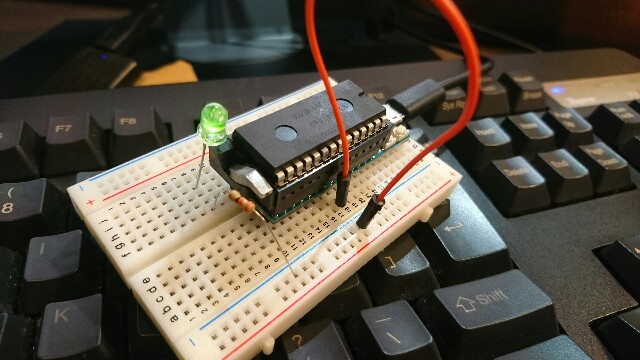
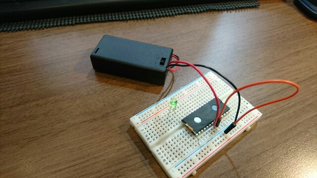
マイコンを取り外した状態で、マイコンと電源で動かす
電源供給が何処なのか、最初よくわからなかったが、
22 Vdd GND
21 Vss 3.3v
ということのようだ。
動作
ステッピングモーターその3 2つのモーターを制御する
2つL6470で、2つのモーターを制御します。
まず、Raspbery Pi 2,3 には、SPI_CE0 と SPI_CE1 があり、2つのSPIデバイスを制御できます。
配線の仕方

上記のように、
SCLK, MISO, MOSI は、共有します。

CE0, CE1 で、どちらか片方を HIGH に、片方を LOW にすることで、制御するデバイスを指定するようです。
BUSY_PIN ですが、独立して数値を読み取る必要がある(はずな)ので、2本用意し、GPIO2箇所に刺しました。
wiringpiでの実装
import wiringpi as wp


wp.wiringPiSPISetup (0, 1000000)
wp.wiringPiSPISetup (1, 1000000


def L6470_write(channel, data):
        data = struct.pack("B", data)
        return wp.wiringPiSPIDataRW(channel, data)

channel = 0
L6470_write(channel, 0x00)
channel = 1
L6470_write(channel, 0x00)
の様に、第一引数に CE0, CE1 の 0, 1 を指定することで、制御するデバイスを指定します。
とりあえず動いたコード
#!/usr/bin/env python
# -*- coding: utf-8 -*-

import wiringpi as wp
import time
import struct
import signal

L6470_SPI_SPEED         = 1000000
STEPPING_TICK           = 200

# BUSY PIN の設定
BUSY_PIN_0      = 21
BUSY_PIN_1      = 20
io = wp.GPIO(wp.GPIO.WPI_MODE_GPIO)
io.pinMode(BUSY_PIN_0,io.INPUT)


def exit_handler(signal, frame):
        # Ctrl+Cが押されたときにデバイスを初期状態に戻して終了する。
        print("\nExit")
        L6470_softstop(0)
        L6470_softstop(1)
        L6470_softhiz(0)
        L6470_softhiz(1)
        quit()

# 終了処理用のシグナルハンドラを準備
signal.signal(signal.SIGINT, exit_handler)

def L6470_write(channel, data):
        data = struct.pack("B", data)
        return wp.wiringPiSPIDataRW(channel, data)

def L6470_init(channel):
        # MAX_SPEED設定。
        # レジスタアドレス。
        L6470_write(channel, 0x07)
        # 最大回転スピード値(10bit) 初期値は 0x41
        L6470_write(channel, 0x00)
        L6470_write(channel, 0x27)

        # KVAL_HOLD設定。
        # レジスタアドレス。
        L6470_write(channel, 0x09)
        # モータ停止中の電圧設定(8bit) 初期値は 0x29
        L6470_write(channel, 0x29)

        # KVAL_RUN設定。
        # レジスタアドレス。
        L6470_write(channel, 0x0A)
        # モータ定速回転中の電圧設定(8bit) 初期値は 0x29
        L6470_write(channel, 0x80)

        # KVAL_ACC設定。
        # レジスタアドレス。
        L6470_write(channel, 0x0B)
        # モータ加速中の電圧設定(8bit) 初期値は 0x29
        L6470_write(channel, 0x80)

        # KVAL_DEC設定。
        # レジスタアドレス。
        L6470_write(channel, 0x0C)
        # モータ減速中の電圧設定(8bit) 初期値は 0x8A
        L6470_write(channel, 0xFF)

        # OCD_TH設定。
        # レジスタアドレス。
        L6470_write(channel, 0x13)
        # オーバーカレントスレッショルド設定(4bit)
        L6470_write(channel, 0x0F)

        # STALL_TH設定。
        # レジスタアドレス。
        L6470_write(channel, 0x14)
        # ストール電流スレッショルド設定(4bit)
        L6470_write(channel, 0x7F)

        # STEP_MODE 設定。
        # レジスタアドレス。
        L6470_write(channel, 0x16)
        # sTEP_MODE設定(8bit) 初期値は 0x07(1/128)
        #L6470_write(channel, 0x07)
        L6470_write(channel, 0x00)

def L6470_run(channel, speed):
        # 方向検出。
        if (speed < 0):
                dir = 0x50
                spd = -1 * speed
        else:
                dir = 0x51
                spd = speed

        # 送信バイトデータ生成。
        spd_h   = (0x0F0000 & spd) >> 16
        spd_m   = (0x00FF00 & spd) >> 8
        spd_l   = (0x0000FF & spd)

        # コマンド(レジスタアドレス)送信。
        L6470_write(channel, dir)
        # データ送信。
        L6470_write(channel, spd_h)
        L6470_write(channel, spd_m)
        L6470_write(channel, spd_l)

def L6470_move(channel, n_step):
        # 方向検出。
        if (n_step < 0):
                dir = 0x40
                stp = -1 * n_step
        else:
                dir = 0x41
                stp = n_step

        # 送信バイトデータ生成。
        stp_h   = (0x3F0000 & stp) >> 16
        stp_m   = (0x00FF00 & stp) >> 8
        stp_l   = (0x0000FF & stp)

        # コマンド(レジスタアドレス)送信。
        L6470_write(channel, dir)
        # データ送信。
        L6470_write(channel, stp_h)
        L6470_write(channel, stp_m)
        L6470_write(channel, stp_l)

        if channel == 0:
                pin     = BUSY_PIN_0
        else:
                pin     = BUSY_PIN_1
        while( io.digitalRead(pin) == 0 ):
                pass

def L6470_softstop(channel):
        print("***** SoftStop. *****")
        dir = 0xB0
        # コマンド(レジスタアドレス)送信。
        L6470_write(channel, dir)
        if channel == 0:
                pin     = BUSY_PIN_0
        else:
                pin     = BUSY_PIN_1
        while( io.digitalRead(pin) == 0 ):
                pass

def L6470_softhiz(channel):
        print("***** Softhiz. *****")
        dir = 0xA8
        # コマンド(レジスタアドレス)送信。
        L6470_write(channel, dir)
        if channel == 0:
                pin     = BUSY_PIN_0
        else:
                pin     = BUSY_PIN_1
        while( io.digitalRead(pin) == 0 ):
                pass

def L6470_getstatus(channel):
        print("***** Getstatus. *****")
        dir = 0xD0
        # コマンド(レジスタアドレス)送信。
        print L6470_write(channel, dir)
        time.sleep(0.2)

if __name__=="__main__":
        speed = 0

        print("***** start spi test program *****")

        # SPI channel を L6470_SPI_SPEED で開始。
        wp.wiringPiSPISetup (0, L6470_SPI_SPEED)
        wp.wiringPiSPISetup (1, L6470_SPI_SPEED)

        # L6470の初期化。
        L6470_init(0)
        L6470_init(1)

        L6470_move(0, 400)
        L6470_move(1, -200)
        L6470_move(0, 800)
        L6470_move(1, -100)
        L6470_move(0, 100)
        L6470_move(1, -200)
        L6470_softstop(0)
        L6470_softstop(1)

        L6470_run(0, 30000)
        L6470_run(1, -30000)
        time.sleep(2)

        L6470_softstop(0)
        L6470_softstop(1)
        L6470_softhiz(0)
        L6470_softhiz(1)
        quit()
課題
上記のコードだと、モーターAのBUSYが解除されるまで、モーターBの制御コードが通らないため、「AとBを同時に 200 Steps 動かす」事ができません。
RUNの場合は、一見同時に動いているように見えますが、スピードが指定速度に達したらBUSYが解除されるので、そう見えるだけで、BUSY解除まで待っているはずです。
スレッドの利用が必要かもしれません。
ステッピングモーターその2 L6470 の機能を試す
L6470の機能を試す。
データシートは以下ですが、
http://strawberry-linux.com/pub/L6470.pdf
日本語訳してくださったサイトが有りました。
Run (DIR, SPD)
0 1 0 1 0 0 0 DIR from host X X X X SP D (Byte 2) from host
SPD (Byte 1) from host
SPD (Byte 0) from host
とあり、
Direction
The Run command produces a motion at SPD speed; the direction is selected by DIR bit: '1' forward or '0' reverse. The SPD value is expressed in step/tick (format unsigned fixed point 0.28) that is the same format that SPEED register (see paragraph 9.1.4).
とある。
DIR bit: '1' forward or '0' reverse.
とのことだから、
0b01010000 = 80 = 0x50 : 逆
0b01010001 = 81 = 0x51 : 順
かな。
BUSY Flag
This command keeps the BUSY flag low until the target speed is reached.
与えらた速度に達するまでは BUSY:LOW になる。
Speed
SPD=5000 の場合は、
0b1001110001000 = 5000 = 0x001388 なので、これを 3 bytes に切り分けると、
0b00000000 0 0x00
0b00010011 19 0x13
0b10001000 136 0x88
になる。
算出の際は、マスク処理をしたたうえで、シフト演算することが多そうだ。
今回は、1バイト目は、半分は使用しないので、マスクは 0x0F0000 になる。
0x0F0000 & spd = 0 = 0x00
0x00FF00 & spd = 4864, (4864 >> 8) = 19 = 0x13
0x0000FF & spd = 136 = 0x88
Move (DIR, N_STEP)
0 1 0 0 0 0 0 DIR from host
X X N_STEP (Byte 2) from host
N_STEP (Byte 1) from host
N_STEP (Byte 0) from host
とあり、Dirにかんしては
The move command produces a motion of N_STEP microsteps; the direction is selected by DIR bit ('1' forward or '0' reverse).
The N_STEP value is always in agreement with the selected step mode; the parameter value unit is equal to the selected step mode (full, half, quarter, etc.).
とある。
Run と一緒だ
'1' forward or '0' reverse
0b01000000 = 64 = 0x40 : 逆
0b01000001 = 65 = 0x41 : 順
BUSY flag
This command keeps the BUSY flag low until the target number of steps is performed.
とあるから、全step移動終わるまでは BUSY:LOW になっている。
そして、
This command can be only performed when the motor is stopped. If a motion is in progress the motor must be stopped and then it is possible to perform a Move command.
Any attempt to perform a Move command when the motor is running causes the command to be ignored and the NOTPERF_CMD flag to rise (see paragraph 9.1.22).
動作完了までは動かないよーと。
N_STEP
まず、使用しているステッピングモーターは、 STEP ANGLE 1.8° 5% だから、200 steps で、一周になる。
つぎに、microsteps の意味ですが、STEP_MODEで決まると。
full, half, quarter, etc とのこと。
Full なら、200 steps で一周だ。
Rest Value は 128 microsteps なので、 128 * 200 = 25600 で一周か。
(レジスタの値は7)
マスクはどうなるかな?
1バイト目のマスクは、 XX000000 になるのだが、表記は、、、調べ中。
001111 のマスクだから 0x3F かな?
0x3F00000 か???
BUSYのチェック
次の処理を入れるために、BUSY flag が終わるまで待ちたいのだが、その方法は?
どうやら、今まで接続してこなかった PIN1 の ~BUSY を使用するようだ。
SetParam(PARAM, VALUE)
ストロベリーリナックスのマニュアルに記述がある。
内部アドレスに書き込むには次のようにします。SetParam(PARAM, VALUE)
8ビットでレジスタアドレスを送信します。これがコマンドバイトになります。その後各レジスタの長さ分引数を与えてくだ
さい。その引数がレジスタに書き込まれます。長さが8ビットで割り切れない場合はMSB 側のビットを0でパディングしま
す。レジスタの長さに応じて引数は1~3バイトとなります。
MAX_SPEED
Address[Hex] Register name Register function Len. [bit] Reset Hex Reset Value Remarks
h07 MAX_SPEED Maximum speed 10 041 248e-6 step/tick(991.8 step/s) R, WR
0x07
0x00
0x41
と、投げれば良さそうだが、なんか変だ。
きちんと速度が変わるケースと、脱調?してしまうことが有る。
reset hex の 0x41 の reset value は 248e-6 step/tick (991.8 step/s) らしい。
STEP_MODE
SYNC_EN(1bit) SYNC_SEL(3bit) 0 STEP_SEL(3bit)
と設定するらしいが、STEP_SELとは?
Table 18. Step mode selection STEP_SEL[2..0] Step mode 0 0 0 Full step
0 0 1 Half step
0 1 0 1/4 microstep
0 1 1 1/8 microstep
1 0 0 1/16 microstep
1 0 1 1/32 microstep
1 1 0 1/64 microstep
1 1 1 1/128 microstep
reset hex の 7 は、 1/128 mode だ。
BUSY PIN
ドライバの PIN 1 の ~BUSY を利用する。
とりあえず、LEDを指して目視で動作を確認すると、平常時は HIGH で、 BUSYな状態だと、 LOW になる。
抜粋ですが
# BUSY PIN の設定
BUSY_PIN        = 21
io = wp.GPIO(wp.GPIO.WPI_MODE_GPIO)
io.pinMode(BUSY_PIN,io.INPUT)


*** 中略 ***

while( io.digitalRead(BUSY_PIN) == 0 ):
    pass
ステッピングモーターその1 モーターとドライバ(L6470)を試す
ステッピングモーターを試します。
モーター、ドライバー、ネジをセットで変えるストロベリーリナックスから購入しました。
L6470 ステッピングモータ・ドライバキット - L6470 - ネット販売
L6470/42x34mmステッピングモーター用ネジセット - ネット販売
別に、ネジを使用する予定はないのですが、買ってみました。
ドキュメントがしっかりしているのが決め手でした。
https://strawberry-linux.com/pub/l6470-manual.pdf
モーター

そもそも、ステッピングモーターの、1相、2相など、コントロールの種類に関しては、事前に勉強が必要。
仕様
 ・2相バイポーラ ステッピングモータ
 ・推奨動作電圧:DC12V
 ・ステップ数:200ステップ(1.8度)
 ・電流:0.33A/相
 ・シャフト径:5mm
 ・シャフト長さ:24mm(方軸)
 ・コイル抵抗:34Ω
 ・重量:200g
 ・保持トルク:0.23N・m
 ・絶縁抵抗:100MΩ以上(500VDC)
 ・サイズ:42(W)x42(H)x34(D)mm
モータードライバ
仕様
コントローラ STMicroelectronics L6470
対応モータ バイポーラ(2相)ステッピングモータ
モータ電源 DC8V~45V
ロジック電源 DC3.3V~5V
最大モータ電流 3A rms (ピーク7A)
インターフェース SPI(4線式)
マイクロステップ数 1/1~1/128の間で設定ができます。
自己消費電流 約5mA(3.3V 動作時)
約1mA(5V動作時) ※実測値
その他機能 3.0Vレギュレータ内蔵,パワーダウンモード,オシレータスリープモード
サイズ 約40x40mm
※このドライバは基本的にモータ電源とロジック電源の2系統の電源を必要とします。
※製作・使用にあたり巻末の使用上の注意をよく読んでお使いください。
SPI の準備
raspi-config から、SPI を有効にします。
9 Advanced option > A5 API から、設定します。
$ lsmod | grep spi
spi_bcm2835             7286  0
$ ls /dev/spidev*
/dev/spidev0.0  /dev/spidev0.1
配線

GPIO 9(SPI MISO)  3(SDO)
GPIO11(SPI SCLK)  5(SCK)
GPIO10(SPI MOSI)  6(DSI)
GPIO 8(SPI CE0)   7(~CS)
なお、CN1インターフェースに、RPIの3.3vとGNDだけをつなぐと、配線した際にOSが落ちました。
モーター電源に電源をつないだ状態で抜き差ししても、落ちません。
配線してある状態でモーターへの給電を止めても、落ちません。
なんとなくですが、ジャンパー設定が「3.3vを給電可能」モードと共通なので、
モーター電源が来ていない場合、その辺がゴニョゴニョしているのかなーと思います。
wiringPi を準備する
インストール
$ git clone git://git.drogon.net/wiringPi
$ cd wiringPi/
$ ./build
コーディング
慣れない C です。
こちらを元に、書き換えました。
起動、加速、減速、解放・・・のつもりです。
http://junkroom2cyberrobotics.blogspot.jp/2012/09/raspberry-pi-spi.html
#include <stdio.h>
#include <stdlib.h>

#include <wiringPi.h>
#include <wiringPiSPI.h>

#define L6470_SPI_CHANNEL 0

// 関数プロトタイプ。
void L6470_write(unsigned char data);
void L6470_init(void);
void L6470_run(long speed);
void L6470_softstop();
void L6470_softhiz();

int main(int argc, char **argv)
{
        int i;
        long speed = 0;

        printf("***** start spi test program *****\n");

        // SPI channel 0 を 1MHz で開始。
        if (wiringPiSPISetup(L6470_SPI_CHANNEL, 1000000) < 0)
        {
                printf("SPI Setup failed:\n");
        }

        // L6470の初期化。
        L6470_init();

        while(1)
        {
                for (i = 0; i < 10; i++)
                {
                        speed += 2000; // 30000 位まで
                        L6470_run(speed);
                        printf("*** Speed %d ***\n", speed);
                        delay (1000);
                }


                for (i= 0; i < 10; i++)
                {
                        speed -= 2000;
                        L6470_run(speed);
                        printf("*** Speed %d ***\n", speed);
                        delay (1000);
                }

                L6470_softstop();
                L6470_softhiz();
                return 0;
        }

        return 0;
}


void L6470_write(unsigned char data)
{
        wiringPiSPIDataRW(L6470_SPI_CHANNEL, &data, 1);
}

void L6470_init()
{
        // MAX_SPEED設定。
        /// レジスタアドレス。
        L6470_write(0x07);
        // 最大回転スピード値(10bit) 初期値は 0x41
        L6470_write(0x00);
        L6470_write(0x41);

        // KVAL_HOLD設定。
        /// レジスタアドレス。
        L6470_write(0x09);
        // モータ停止中の電圧設定(8bit)
        L6470_write(0xFF);

        // KVAL_RUN設定。
        /// レジスタアドレス。
        L6470_write(0x0A);
        // モータ定速回転中の電圧設定(8bit)
        L6470_write(0xFF);

        // KVAL_ACC設定。
        /// レジスタアドレス。
        L6470_write(0x0B);
        // モータ加速中の電圧設定(8bit)
        L6470_write(0xFF);

        // KVAL_DEC設定。
        /// レジスタアドレス。
        L6470_write(0x0C);
        // モータ減速中の電圧設定(8bit) 初期値は 0x8A
        L6470_write(0x40);

        // OCD_TH設定。
        /// レジスタアドレス。
        L6470_write(0x13);
        // オーバーカレントスレッショルド設定(4bit)
        L6470_write(0x0F);

        // STALL_TH設定。
        /// レジスタアドレス。
        L6470_write(0x14);
        // ストール電流スレッショルド設定(4bit)
        L6470_write(0x7F);
}

void L6470_run(long speed)
{
        unsigned short dir;
        unsigned long spd;
        unsigned char spd_h;
        unsigned char spd_m;
        unsigned char spd_l;

        // 方向検出。
        if (speed < 0)
        {
                dir = 0x50;
                spd = -1 * speed;
        }
        else
        {
                dir = 0x51;
                spd = speed;
        }

        // 送信バイトデータ生成。
        spd_h = (unsigned char)((0x0F0000 & spd) >> 16);
        spd_m = (unsigned char)((0x00FF00 & spd) >> 8);
        spd_l = (unsigned char)(0x00FF & spd);

        // コマンド(レジスタアドレス)送信。
        L6470_write(dir);
        // データ送信。
        L6470_write(spd_h);
        L6470_write(spd_m);
        L6470_write(spd_l);
}

void L6470_softstop()
{
        unsigned short dir;
        printf("***** SoftStop. *****\n");
        dir = 0xB0;
        // コマンド(レジスタアドレス)送信。
        L6470_write(dir);
        delay(1000);
}

void L6470_softhiz()
{
        unsigned short dir;
        printf("***** Softhiz. *****\n");
        dir = 0xA8;
        // コマンド(レジスタアドレス)送信。
        L6470_write(dir);
        delay(1000);
}
gcc -o wir wir.c -I /usr/local/include -L /usr/local/lib -l wiringPi
最後のsoftstopは、意味ないですし、whileも意味ないですが、
動作差テストには成るかなと。
softstop/hardstop の状態は、トルクを維持しますので、電磁石はONの状態。
発熱します。
HiZ します。
データシート曰く、softhiz は、 10100000 なので、16進数に直すと、A8 に成ります。
wiringpi2 を Python で使う
インストール
$ sudo pip install wiringpi2
動作チェック
$ sudo python
Python 2.7.9 (default, Mar  8 2015, 00:52:26)
[GCC 4.9.2] on linux2
Type "help", "copyright", "credits" or "license" for more information.
>>> import wiringpi
>>> wiringpi.piBoardRev()
2
>>> wiringpi.wiringPiSetup()
0
>>> quit()
コーディング
wiringpi wiringPiSPIDataRW が、2つの引数のみを受け付けるのだが、一体何を渡せばいいのかわからず、調べた。
ソースを読むと、Cにそのまま第2変数を投げているだけに見える・・・。
Gadgetoid commented on 2 Apr 2013 Amazingly late to the game here, but I have started maintaining WiringPi again in the form of a new version which you can find here: https://github.com/WiringPi/WiringPi2-Python The function wiringPiSPIDataRW now takes two arguments, pin and the string. Length and conversion to the correct datatype is handled internally. You should be able to call it thus: wiringPiSPIDataRW(1,'badger') I am the sole maintainer of this package, and had more pressing distractions. I'm tremendously late in getting it updated and offer my apologies. I'd love to see you guys come back to WiringPi2-Python and test it out; I'll be around to attempt to fix any problems you might have.
Pin, String らしい。
別のスレッドも探してみたら、
Python 2.7 なら、 (Int Pin, Str Data ) もしくは (Int Pin, Chr Data )で、
Python 3 なら、(Int Pin, Bytes Data)
らしい。
2.7 系で、 Str Data とうことだが、255 = 0xFF を Strで渡すというのは、"0xFF" を渡すのか、 "FF" を渡すのか、、、。
試行錯誤の結果として、
とりあえず、0xFF (int型)を、struct.pack で、ununsigned char型に変換して投げるようにしたら、動いた・・・。
これで正しいのだろうか。
#!/usr/bin/env python
# -*- coding: utf-8 -*-

import wiringpi as wp
import time
import struct

L6470_SPI_CHANNEL       = 0
L6470_SPI_SPEED         = 1000000

def L6470_write(data):
        data = struct.pack("B", data)
        wp.wiringPiSPIDataRW(L6470_SPI_CHANNEL, data)

def L6470_init():
        # MAX_SPEED設定。
        # レジスタアドレス。
        L6470_write(0x07)
        # 最大回転スピード値(10bit) 初期値は 0x41
        L6470_write(0x00)
        L6470_write(0x41)

        # KVAL_HOLD設定。
        # レジスタアドレス。
        L6470_write(0x09)
        # モータ停止中の電圧設定(8bit)
        L6470_write(0xFF)

        # KVAL_RUN設定。
        # レジスタアドレス。
        L6470_write(0x0A)
        # モータ定速回転中の電圧設定(8bit)
        L6470_write(0xFF)

        # KVAL_ACC設定。
        # レジスタアドレス。
        L6470_write(0x0B)
        # モータ加速中の電圧設定(8bit)
        L6470_write(0xFF)

        # KVAL_DEC設定。
        # レジスタアドレス。
        L6470_write(0x0C)
        # モータ減速中の電圧設定(8bit) 初期値は 0x8A
        L6470_write(0x40)

        # OCD_TH設定。
        # レジスタアドレス。
        L6470_write(0x13)
        # オーバーカレントスレッショルド設定(4bit)
        L6470_write(0x0F)

        # STALL_TH設定。
        # レジスタアドレス。
        L6470_write(0x14)
        # ストール電流スレッショルド設定(4bit)
        L6470_write(0x7F)

def L6470_run(speed):
        # 方向検出。
        if (speed < 0):
                dir = 0x50
                spd = -1 * speed
        else:
                dir = 0x51
                spd = speed

        # 送信バイトデータ生成。
        spd_h   =  (0x0F0000 & spd) >> 16
        spd_m   =  (0x00FF00 & spd) >> 8
        spd_l   =  (0x00FF & spd)

        # コマンド(レジスタアドレス)送信。
        L6470_write(dir)
        # データ送信。
        L6470_write(spd_h)
        L6470_write(spd_m)
        L6470_write(spd_l)

def L6470_softstop():
        print("***** SoftStop. *****")
        dir = 0xB0
        # コマンド(レジスタアドレス)送信。
        L6470_write(dir)
        time.sleep(1)

def L6470_softhiz():
        print("***** Softhiz. *****")
        dir = 0xA8
        # コマンド(レジスタアドレス)送信。
        L6470_write(dir)
        time.sleep(1)

if __name__=="__main__":
        speed = 0

        print("***** start spi test program *****")

        # SPI channel 0 を 1MHz で開始。
        #wp.wiringPiSetupGpio()
        wp.wiringPiSPISetup (L6470_SPI_CHANNEL, L6470_SPI_SPEED)

        # L6470の初期化。
        L6470_init()

        while True:
                for i in range(0, 10):
                        speed = speed + 2000 # 30000 位まで
                        L6470_run(speed)
                        print("*** Speed %d ***" % speed)
                        time.sleep(1)

                for i in range(0, 10):
                        speed = speed - 2000
                        L6470_run(speed)
                        print("*** Speed %d ***" % speed)
                        time.sleep(1)

                L6470_softstop()
                L6470_softhiz()
                quit()
        quit()