Raspberry pi でロボットアームを動かす その5 ウェブカメラと画像解析
アームの先端にWEBカメラを付けて、認識させてみる
まず、動作確認その他めのために、Displayを取得したい。
X11VNC でリモートデスクトップ
最初 xrdp でリモートデスクトップ接続していたのですが、Xlib: extension “RANDR” missing on display “:1.0” とでて、対処の仕方がわからなかったので、X11VNC に切り替えました。
画面に出ている映像を取得する感じなので、自動で xwindow まで到達させておきます。
/etc/lightdm/lightdm.conf で、ログインさせておきたいユーザーを指定。
解像度指定
/boot/config.txt frambebuffer の2行。
$ sudo apt-get install x11vnc
$ x11vnc
ポートが出るので、わかりますが、初回なら 5900 でしょう。
一旦切断?した後、再度接続する際には、
$ x11vnc
します。
x11vnc 自動起動
cat .config/autostart/x11vnc.desktop
[Desktop Entry]
Encoding=UTF-8
Type=Application
Name=X11VNC
Comment=X11VNC
Exec=x11vnc
StartupNortify=false
Terminal=false
Hidden=false
opencv のインストール
$ sudo apt-get install libopencv-dev
$ sudo apt-get install python-opencv
opencv のテスト
適当な画像を読み込んで、処理して、x-window に window を出すテストを行う。
realvnc などで、接続しておく。
RBG を HSV に変換 & 2値化
境界線の抽出
OpenCV: Contours : Getting Started
コーディング
contour が複数ある際にどうするかですが、今回は単純に一番大きな四角だけを拾うようにしました。
#!/usr/bin/env python
# -*- coding: utf-8 -*
import sys
import cv2
import numpy as np
import pprint as pp

def main():
        image = cv2.imread('001.png')
        cv2.namedWindow("original");
        cv2.moveWindow("original", 10, 50);
        cv2.imshow('original', image)
        cv2.waitKey(0)
        cv2.destroyAllWindows()

        image_hsv = cv2.cvtColor(image, cv2.COLOR_BGR2HSV)      # HSV, range of Hue is 0-180
        #image_hsv = cv2.cvtColor(image, cv2.COLOR_BGR2HSV_FULL)        # HSV_FULL, range of Hue is 0-360
#       pp.pprint(image_hsv)

        h = image_hsv[:, :, 0]
        s = image_hsv[:, :, 1]
        v = image_hsv[:, :, 2]

        width   = h[0,:].size
        height  = h[:,0].size
        print( 'width %s, height %s' % (width, height) )

        blue_min = np.array([110, 100, 100], np.uint8)
        blue_max = np.array([140, 255, 255], np.uint8)
        threshold_blue_img = cv2.inRange(image_hsv, blue_min, blue_max)

        cv2.namedWindow("threshold_blue_img");
        cv2.moveWindow("threshold_blue_img", 10, 50);
        cv2.imshow('threshold_blue_img', threshold_blue_img)
#       cv2.imwrite("threshold_blue_img.png", threshold_blue_img);
        cv2.waitKey(0)
        cv2.destroyAllWindows()

#       pp.pprint(threshold_blue_img)
        contours,hierarchy = cv2.findContours(threshold_blue_img,cv2.RETR_TREE,cv2.CHAIN_APPROX_SIMPLE)
#       pp.pprint(contours)

        cv2.namedWindow("contours");
        cv2.moveWindow("contours", 10, 50);
        cv2.drawContours(image, contours,-1,(0,255,0),3)
        cv2.imshow('contours', image)
#       cv2.imwrite("contours.png", image);
        cv2.waitKey(0)
        cv2.destroyAllWindows()

        rects = []
        for contour in contours:
                approx = cv2.convexHull(contour)
                rect = cv2.boundingRect(approx) # x,y,w,h
                rects.append(rect)
        pp.pprint( rects )

        biggest_rect        = getBiggestRect( rects )

        center_x        = biggest_rect[0] + biggest_rect[2]/2
        center_y        = biggest_rect[1] + biggest_rect[3]/2

        image = cv2.imread('001.png')
        cv2.rectangle(image, (biggest_rect[0], biggest_rect[1]), (biggest_rect[0]+biggest_rect[2], biggest_rect[1]+biggest_rect[3]), (0, 0, 255), 1[f:id:pongsuke:20170130171525p:plain])
        cv2.line(image, (center_x, 0), (center_x, height), (0, 0, 255)) # Draw Red Line
        cv2.line(image, (0, center_y), (width, center_y), (0, 0, 255)) # Draw Red Line
        cv2.imshow('Line', image)
#       cv2.imwrite("Line.png", image);
        cv2.moveWindow("Line", 10, 50);
        cv2.waitKey(0)
        cv2.destroyAllWindows()

def getBiggestRect( rects ):
        pre_area        = 0
        biggest_index   = 0
        for i, rect in enumerate(rects):
                area    = rect[2] * rect[3]
                if area > pre_area:
                        pre_area        = area
                        biggest_index   = i
        return rects[biggest_index]

if __name__ == '__main__':
        try:
                main()
        except KeyboardInterrupt:
                sys.exit(0)
実行結果
オリジナルの画像(風景写真に、青の丸を3つ書き込んであります。)

青とそれ以外の2値化後

contours

一番大きな四角を拾う

opencv と ウェブカメラ
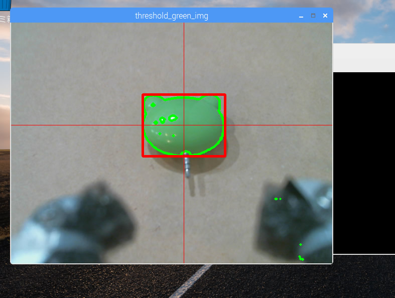
緑で2値化して、輪郭抽出して、1番大きな四角で囲みます。
#!/usr/bin/python
# coding: utf-8

import sys
import cv2
import numpy as np
import pprint as pp

cap = cv2.VideoCapture(0)

def capture_camera():
        green_min = np.array([40, 70, 70], np.uint8)
        green_max = np.array([80, 255, 255], np.uint8)
        while True:
                ret, frame = cap.read()


                # 2値化
                image_hsv = cv2.cvtColor(frame, cv2.COLOR_BGR2HSV)      # HSV, range of Hue is 0-180
                h = image_hsv[:, :, 0]
                s = image_hsv[:, :, 1]
                v = image_hsv[:, :, 2]
                width   = h[0,:].size
                height  = h[:,0].size
#               print( 'width %s, height %s' % (width, height) )

                threshold_green_img = cv2.inRange(image_hsv, green_min, green_max)
                # 輪郭抽出
                contours, hierarchy = cv2.findContours(threshold_green_img,cv2.RETR_TREE,cv2.CHAIN_APPROX_SIMPLE)
#               pp.pprint( contours )

                cv2.drawContours(frame, contours, -1, (0,255,0), 3)

                if len(contours) > 0 :
                        rects = []
                        for contour in contours:
                                approx = cv2.convexHull(contour)
                                rect = cv2.boundingRect(approx) # x,y,w,h
                                rects.append(rect)
                        pp.pprint( len(rects) )
                        max_rect        = getBiggestRect( rects )
                        center_x        = max_rect[0] + max_rect[2]/2
                        center_y        = max_rect[1] + max_rect[3]/2
                        # 囲む
                        cv2.rectangle(frame, (max_rect[0], max_rect[1]), (max_rect[0]+max_rect[2], max_rect[1]+max_rect[3]), (0, 0, 255), 3)
                        # 線を引く
                        cv2.line(frame, (center_x, 0), (center_x, height), (0, 0, 255)) # Draw Red Line
                        cv2.line(frame, (0, center_y), (width, center_y), (0, 0, 255)) # Draw Red Line

                cv2.imshow('threshold_green_img', frame)

                #frameを表示
                #cv2.imshow('camera capture', frame)

                #10msecキー入力待ち
                k = cv2.waitKey(10)
                #Escキーを押されたら終了
                if k == 27:
                        break

def getBiggestRect( rects ):
        pre_area        = 0
        biggest_index   = 0
        for i, rect in enumerate(rects):
                area    = rect[2] * rect[3]
                if area > pre_area:
                        pre_area        = area
                        biggest_index   = i
        return rects[biggest_index]


if __name__ == '__main__':
        try:
                while True:
                        capture_camera()
                        break

        except KeyboardInterrupt:
                        pass

#キャプチャを終了
cap.release()
cv2.destroyAllWindows()
実行
電圧計を使ってみる & ピンプラグ給電を試す
テスターではなく、電圧計を使ってみます。
電圧計その1
まず、1つ250円のこちら。
超小型2線式LEDデジタル電圧計(パネルメータ)3桁表示 DC3〜15V(赤色)オートレンジ: 測定器・計測器関連 秋月電子通商 電子部品 ネット通販
まず、安定化電源で 3.4v をだして、電圧計をチェック。

Raspberry pi 5v を計測しました。
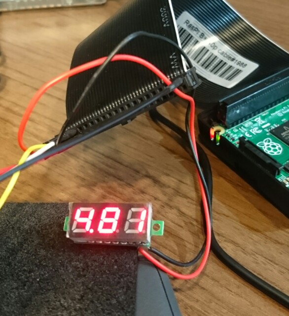
結構低いです。
電圧計その2
USBタイプです。
多機能USB簡易電圧・電流チェッカー(積算電流・電力・時間表示対応) RT−USBVAC3QC: 測定器・計測器関連 秋月電子通商 電子部品 ネット通販
WEBカメラを刺してみました。
これは、刺しているだけで、動作はさせていない状態です。
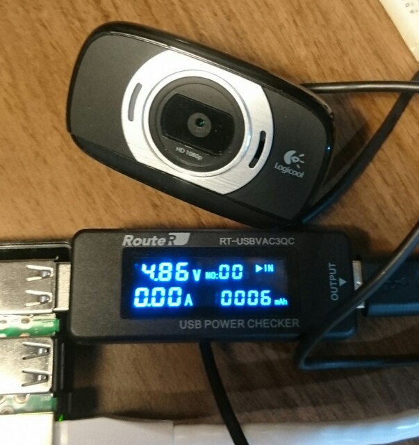
次に、MjewpStreamer でストリーミングしてみた。

ピンプラグ給電を試します
GPIOの 5v と GND に5vを供給して起動します。
3.3vに繋いだら、多分壊れる。
ACアダプター
5v 4A を買った。
とりあえず電圧を測定してみる。

5.2v出てます。
大丈夫かな・・・。
カメラ接続だけ。

カメラ起動中

高く与えた電圧の分、高くなっている。
Raspberry pi でロボットアームを動かす その4 接続と動作テスト
MG996R も、DS3218 も、可動域が違いますがほぼ一緒です。
PCA9685 で、60hzで全部動かしちゃいます。
150 で最小値、 600 で最大値 を取ってくれる、、、みたいです。
可動域
MG996R 120度
DS3218 180度
ちなみに、可動域を超えて動かそうとすると、すごい発熱します!
ハンドの部分は、モーターの可動域そのままは使用しません。
ハンドの可動域を超えて動こうとして壊れないように、範囲を限定して動かします。
私の場合は
min     = 250
max     = 395
です。
コーディング
ハンド以外も、パーセント指定で動かせたほうが楽かと思い、書き直しました。
#!/usr/bin/python
# coding: utf-8

from __future__ import division
import time
import Adafruit_PCA9685

# Uncomment to enable debug output.
#import logging
#logging.basicConfig(level=logging.DEBUG)

pwm = Adafruit_PCA9685.PCA9685()
pwm.set_pwm_freq(60)

def MG996R_BASE( percent ):
        channel = 0
        min     = 150
        max     = 600
        a_percent       = (max-min)/100
        pwm.set_pwm(channel, 0, int(a_percent*percent)+min)

def DS3218_LEAN_UNDER( percent ):
        percent = 100 - percent
        channel = 1
        min     = 250
        max     = 500
        a_percent       = (max-min)/100
        pwm.set_pwm(channel, 0, int(a_percent*percent)+min)

def MG996R_LEAN_UPPER( percent ):
        channel = 2
        min     = 150
        max     = 500
        a_percent       = (max-min)/100
        pwm.set_pwm(channel, 0, int(a_percent*percent)+min)

def MG996R_WRIST( percent ):
        channel = 3
        min     = 150
        max     = 600
        a_percent       = (max-min)/100
        pwm.set_pwm(channel, 0, int(a_percent*percent)+min)

def MG996R_HAND( percent ):
        channel = 4
        min     = 250
        max     = 395
        a_percent       = (max-min)/100
        pwm.set_pwm(channel, 0, int(a_percent*percent)+min)

def calibration():
        MG996R_BASE(0)
        time.sleep(1)
        MG996R_BASE(50)
        time.sleep(1)
        MG996R_BASE(100)
        time.sleep(1)
        MG996R_BASE(50)
        time.sleep(1)

        DS3218_LEAN_UNDER(0)
        time.sleep(1)
        DS3218_LEAN_UNDER(50)
        time.sleep(1)
        DS3218_LEAN_UNDER(100)
        time.sleep(1)
        DS3218_LEAN_UNDER(50)
        time.sleep(1)

        MG996R_LEAN_UPPER(0)
        time.sleep(1)
        MG996R_LEAN_UPPER(50)
        time.sleep(1)
        MG996R_LEAN_UPPER(100)
        time.sleep(1)
        MG996R_LEAN_UPPER(10)
        time.sleep(1)

        MG996R_WRIST(0)
        time.sleep(1)
        MG996R_WRIST(50)
        time.sleep(1)
        MG996R_WRIST(100)
        time.sleep(1)
        MG996R_WRIST(50)
        time.sleep(1)

        MG996R_HAND( 5 )
        time.sleep(1)
        MG996R_HAND( 95 )
        time.sleep(1)

def move01():
        MG996R_HAND(80)
        time.sleep(1)
        MG996R_HAND(0)
        time.sleep(1)
        DS3218_LEAN_UNDER(20)
        time.sleep(1)
        MG996R_BASE(40)
        time.sleep(1)
        MG996R_BASE(48)
        time.sleep(1)
        MG996R_LEAN_UPPER(10)
        time.sleep(1)
        MG996R_LEAN_UPPER(18)
        time.sleep(1)

        time.sleep(2)

        for var in range(0, 4):
                MG996R_HAND(10)
                time.sleep(0.5)
                MG996R_HAND(90)
                time.sleep(0.5)

if __name__ == '__main__':
        try:
                while True:
                        #calibration()
                        move01()
                        break

        except KeyboardInterrupt:
                pass

MG996R_BASE(50)                 # 旋回
time.sleep(0.5)
DS3218_LEAN_UNDER(80)   # 傾斜・下
time.sleep(0.5)
MG996R_LEAN_UPPER(10)   # 傾斜・上
time.sleep(0.5)
MG996R_WRIST(50)                #ハンド回転
time.sleep(0.5)
MG996R_HAND( 50 )               # ハンド開閉
time.sleep(0.5)
print("END.\n")
電源の交換
それぞれ独立して動かす分には、6V 2A で足りることがわかったので、別途用意した ACアダプター(6V 2.8A)を使用することにしました。
動作も問題無さそうです。
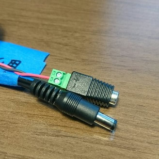
以下の2つを使用しました。
スイッチングACアダプター6V2.8A 100V〜240V GF18−US0628−T: 電源一般 秋月電子通商 電子部品 ネット通販
2.1mm標準DCジャック⇔小型ねじ端子台(着脱可能): パーツ一般 秋月電子通商 電子部品 ネット通販
Raspberry pi でロボットアームを動かす その3 PCA9685
I2C接続16チャンネル サーボ&PWM駆動キット PCA9685 を試す
はんだ付け
先にPINを付けてから、電源のターミナルをつける。
そうしないと、裏返した際に傾いて、はんだ付けしにくい。
配線
SCL - RPI GPIO3
SDA - RPI GPIO2
GND - RPI GND
Vcc - RPI 5v
I2C を有効にする
raspi-config から行う。
動作確認
$ sudo i2cdetect -y 1
     0  1  2  3  4  5  6  7  8  9  a  b  c  d  e  f
00:          -- -- -- -- -- -- -- -- -- -- -- -- --
10: -- -- -- -- -- -- -- -- -- -- -- -- -- -- -- --
20: -- -- -- -- -- -- -- -- -- -- -- -- -- -- -- --
30: -- -- -- -- -- -- -- -- -- -- -- -- -- -- -- --
40: 40 -- -- -- -- -- -- -- -- -- -- -- -- -- -- --
50: -- -- -- -- -- -- -- -- -- -- -- -- -- -- -- --
60: -- -- -- -- -- -- -- -- -- -- -- -- -- -- -- --
70: 70 -- -- -- -- -- -- --
Adafruitのライブラリとサンプルを使う。
$ git clone https://github.com/adafruit/Adafruit_Python_PCA9685.git
$ cd Adafruit_Python_PCA9685
$ sudo python setup.py install
サンプルスクリプトを書き換える。
0と1に繋いであります。
$ cat PCA9685.py
#!/usr/bin/python
# coding: utf-8

from __future__ import division
import time
import Adafruit_PCA9685

# Uncomment to enable debug output.
#import logging
#logging.basicConfig(level=logging.DEBUG)

pwm = Adafruit_PCA9685.PCA9685()

def set_servo_pulse(channel, pulse):
        pulse_length = 1000000    # 1,000,000 us per second
        pulse_length //= 50       # Hz
        print('{0}us per period'.format(pulse_length))
        pulse_length //= 4096     # 12 bits of resolution
        print('{0}us per bit'.format(pulse_length))
        pulse /= pulse_length
        print "%d pulse" % pulse
        pwm.set_pwm(channel, 0, int(pulse))

pwm_set = [800, 1200]

if __name__ == '__main__':
        try:
                while True:
                        channel = 0
                        set_servo_pulse(channel, pwm_set[0])
                        time.sleep(1)
                        set_servo_pulse(channel, pwm_set[1])
                        time.sleep(1)

                        channel = 1
                        set_servo_pulse(channel, pwm_set[0])
                        time.sleep(1)
                        set_servo_pulse(channel, pwm_set[1])
                        time.sleep(1)

        except KeyboardInterrupt:
                pass
スクリプトその2
モーターの仕様に合わせて、50hzにしたり、DUty比を計算して値を当ててみたりしたんですが、どうも、PCA9685 と、Adafruitさんのドライバにおいては、サンプルに有るように、 60hz, 150最小, 600最大 で組んでしまったほうが良さそうです。
ドライバの詳細を読み込めば、分かるのかもしれませんが、現在の結論は、そうなってしまった。
$ cat PCA9685.py
#!/usr/bin/python
# coding: utf-8

from __future__ import division
import time
import Adafruit_PCA9685

# Uncomment to enable debug output.
#import logging
#logging.basicConfig(level=logging.DEBUG)

pwm = Adafruit_PCA9685.PCA9685()
pwm.set_pwm_freq(60)

if __name__ == '__main__':
        try:
                while True:
                        channel = 0
                        pwm.set_pwm(channel, 0, 150)
                        time.sleep(1)
                        pwm.set_pwm(channel, 0, 375)
                        time.sleep(1)
                        pwm.set_pwm(channel, 0, 600)
                        time.sleep(1)
                        pwm.set_pwm(channel, 0, 375)
                        time.sleep(1)

                        channel = 1
                        pwm.set_pwm(channel, 0, 150)
                        time.sleep(1)
                        pwm.set_pwm(channel, 0, 375)
                        time.sleep(1)
                        pwm.set_pwm(channel, 0, 600)
                        time.sleep(1)
                        pwm.set_pwm(channel, 0, 375)
                        time.sleep(1)


        except KeyboardInterrupt:
                pass

pwm.set_pwm(0, 0, 375)
time.sleep(1)
pwm.set_pwm(1, 0, 375)
time.sleep(1)
print("END.\n")
モーターをゼロポジションにする
上記のスクリプトで、とにかく 375 で終了にさせておく。
ただし、下から3つ目のサーボモーターは、設計図のままだと、可動域の中央ではない。
上を向かせて組まないといけない。
アームを組み上げる
これの、1:19 あたりから5軸の組み立て方が出ます。
最初は3軸用なので注意。
注意点!
1.ネジとホーンの種類
サーボモーターと一緒に入っているネジとホーン(5袋)は使用しません。
別の袋に入っている、金属のホーンと、その復路に貼っているネジで組み上げます。
2. ネジの長さが長すぎる
とくに、ハンドの部分。
ホーンの厚みよりもネジが長いので、当たっちゃいます。
ペンチでカットしました。
3. ハンドの可動域
120度全て動かせません。(開きすぎちゃう)
渡しの場合は、DUry比で50%で組合上げて、色々ずれて? 結局、
min = 250
max = 395
と成りました。
min で閉じて、 max で開き切ります。
なので、それ以上、それ以下にならないようにコーディングします。

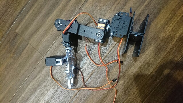
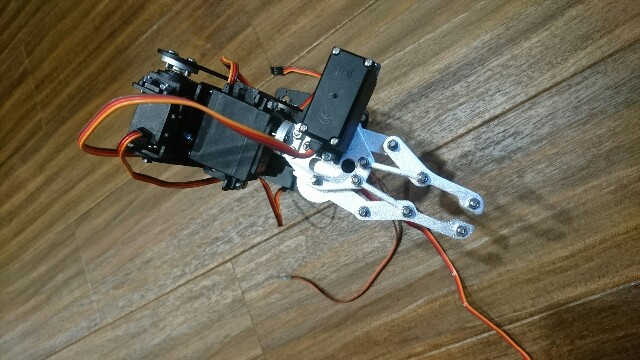
Raspberry pi でロボットアームを動かす その2
モーターの動作確認
MG996R の動作確認
6v 1A に設定した安定化電源から給電しました。
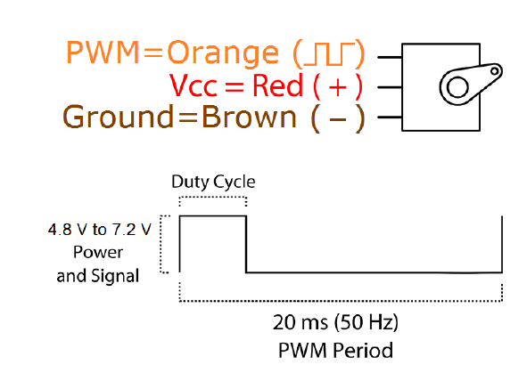
配線は、上記の通り。
周波数も、上記の通り 50hz です。
$ cat MG996R.py
#!/usr/bin/python
# coding: utf-8

import RPi.GPIO as GPIO
import time
import sys

# GPIO 21番を使用
PIN = 21

GPIO.setmode(GPIO.BCM)
GPIO.setup(PIN, GPIO.OUT)
servo = GPIO.PWM(PIN, 50)       # GPIO.PWM(PIN, [周波数(Hz)])

val = [2.5,3.6875,4.875,6.0625,7.25,8.4375,9.625,10.8125,12]

if __name__ == '__main__':
        try:
                servo.start(0.0)

                servo.ChangeDutyCycle(val[0])
                time.sleep(0.5)
                servo.ChangeDutyCycle(val[8])
                time.sleep(0.5)
                servo.ChangeDutyCycle(val[0])
                time.sleep(0.5)

                while True:
                        for i, dc in enumerate(val):
                                servo.ChangeDutyCycle(dc)
                                print("Angle:" + str(i*22.5)+"  dc = %.4f" % dc)
                                time.sleep(0.5)
                        for i, dc in enumerate( reversed(val) ):
                                servo.ChangeDutyCycle(dc)
                                print("Angle:" + str(180 - i*22.5)+"  dc = %.4f" % dc)
                                time.sleep(0.5)

        except KeyboardInterrupt:
                pass

servo.ChangeDutyCycle(val[4])
time.sleep(1.5)
servo.stop()
GPIO.cleanup()
DS3218
安定化電源(6v, 1A設定)につないで、RPIからPWMを送るのですが、どうもピクピクしてしまう。
試しに RPI 5v から給電した所、正常に動いた。
ただし、電圧低下のシグナルが出るので、このままでは良くない。
しばらく原因がわからなかったのですが、どうも、ただのアンペア不足だったようです。2A出すようにしたら、正常に動き始めました。
流す電流も大きくなってきたので、PCA9685 を入れることにしました。
Raspberry pi でロボットアームを動かす その1
ロボットアームを動かしてみたい。
色々とロボットアームを検討したのですが、最終的に、これを日本のAmazonで買った。

5軸だ。
使用するモーター
4 x 9kg servo = Tower Pro, MG996R 55g metal gear servo * 4
1 x 20kg servo = DS3218
だ。
MG996R
データシート曰く、
Specifications
 Weight: 55 g
 Dimension: 40.7 x 19.7 x 42.9 mm approx.
 Stall torque: 9.4 kgf・cm (4.8 V ), 11 kgf・cm (6 V)
 Operating speed: 0.17 s/60o (4.8 V), 0.14 s/60o (6 V)
 Operating voltage: 4.8 V a 7.2 V
 Running Current 500 mA - 900 mA (6V)
 Stall Current 2.5 A (6V)
 Dead band width: 5 μs
 Stable and shock proof double ball bearing design
 Temperature range: 0 oC - 55 oC
1.0Aは見ておいたほうが良いのだろう。
同時に複数箇所動かすのは、電流が足りなくなりそう。

DS3218
データシートが見つからないが、下記のサイトが詳しい。
消える前に引用しておく。
LD-1501MG 17KGロボット用180度高トルクデジタルサーボ セール - バングッド
Specifications:
- Weight: 60g
- Size: 40*20*40.5mm
- Speed: 0.16sec/60 7.4V
- Nm: 15kg/cm 6V ; 17kg/cm 7.4V
- Work voltage: 6-7.4V
- Cable length: 30cm
- Accessories includes plastic servo horm and servo arm, screws, rubber sleeve, etc
Rotation Angle: maximum 180 degree

Instruction:
PWM pulse width adjustment angle, the period is 20ms, duty cycle 0.5ms~2.5ms of the pulse width level corresponding to 0 degree -180 degree, that is a linear relationship. Usually the servo actuator controller uses 500-2500 value corresponding to the servo control of the output angle of the duty ratio of 0.5ms~2.5ms, so that the control accuracy of the LD-1501MG servo is 3us, the minimum control accuracy can reach 0.3 degrees within the 2000 pulse width!
20ms周期 = 50hz
  0度 = 0,5ms = 0.5/20 = 2.5%
180度 = 2.0ms =  2/20 = 10.0%
電流に関して
MG996R 6v, DS3218 6v で良さそうだ。
USB 5v で完結すると理想的だ。
USB 5v を 6b に昇圧させれば良いんだろうとは思うが、そもそも、USBには 5v 2.5A 程度が最大だ。
どのみち1つのUSBでは動かせないだろう・・・。
DC-DCコンバーター も視野に入れつつ、とりあえずは、手元にある 2.5A までの安定化電源でテストしようと思う。
Raspberry pi Zero で オフィス環境の可視化 その4
ロギングしたので、グラフにしました。


